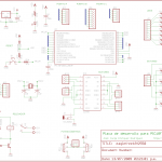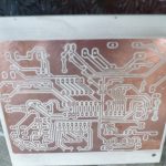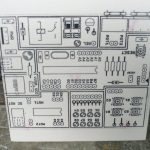
This is a development board for the PIC18F2550, I designed this board inspired by the TP-2550 development board by Giovanni Lafebre (site is in Spanish). Main difference between the original and my design is the size, mine is 10×8 cm, so it has less elements. This is because I created this board using the free version of Eagle, so I adjusted to its restrictions.
Eaglefree18f2550 features:
- 8 LEDs.
- 4 push buttons with pull-down 220Ω resistors.
- 2 potentiometers.
- 1 relay with an active LED indicator. For using the relay, you must provide an external power supply.
- 1 H bridge.
- 1 barrel connector for H bridge power supply.
- The board can be supplied from the USB or from an external supply (jumper selectable).
- 5V regulator onboard.
- ICSP port for PIC programming.
- Jumper for enabling/disabling programmer voltage. This allows for the programmer to be powered from the board supply, so we can have the programmer plugged to the board all the time.
Get the Eagle project from this link: [download id=”1994″]
Some pictures:

schematic |

pcb design |

bottom side |

top side |

almost finished |

with PICkit2 |

eagle3d render, created by Alex |
||
I’ve been using this board for several projects and testing, this is my first development board and I’m really happy with it, it makes the testing process so much faster (and easier) :).
However, I must say I found some details:
- I’ve done two repairs: a pad of the USB connector lifted from the PCB, and so did one of the power LED. I guess the former was caused by movement because the connector was not perfectly fixed to the PCB, but I have no idea for the latter, maybe copper was too thin.
- When working with the board, I’ve needed Vdd and Vss connections, however, they’re not easily available in my design (TP-2550 has dedicated connections for these), I had to hook up wires to the ICSP connector.
- I haven’t used the relay output as much as I thought, maybe I could replace it for another and more useful component.
- The pot model I used in the design did not match the ones I finally soldered to the PCB, so they’re too close (actually, they “touch” each other), something I forgot to check :p.
Anyway, these are some observations I’ll take into account for next version, or maybe you can improve it 🙂 (if so, please let me know).
can u mail me the mplab(cirucit) and the pcb layout files i need it as early as possible..hope ull..see to ur juniors
do you give training also for this board using.
If yes please call me on 9890512532 -Pritam